One Ring to Rule Them All: Wiring Radios to Laptops the Hard Way
Marek Majkowski
58 minutes ago
9 min read
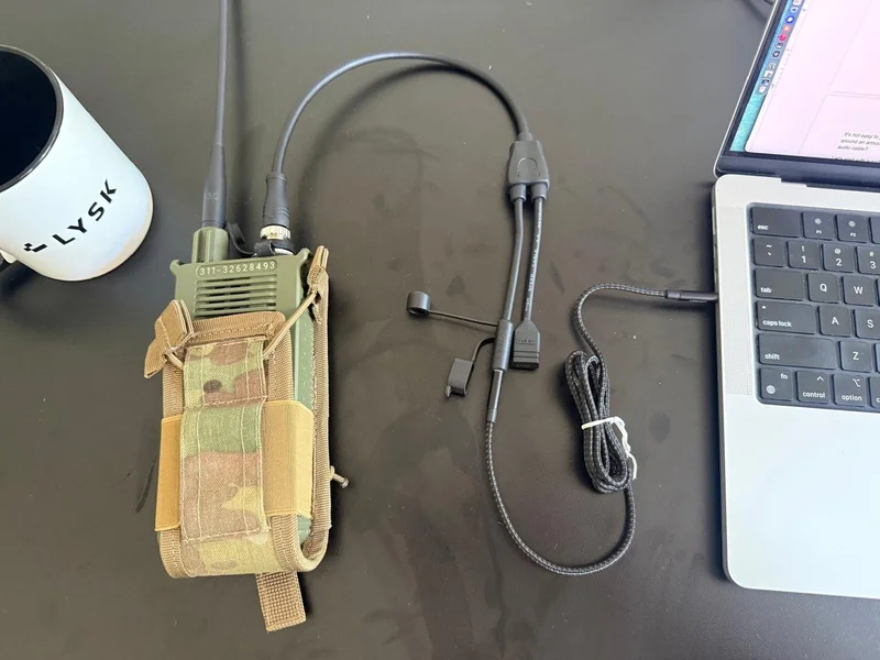
At Lysk, we process and analyse military voice communications. In other words: we plug radios into computers. This is typically done with an AUX audio cable: a proprietary connector to the rugged radio on one side, and a humble minijack plug on the other.
Getting the cabling right to run our software is surprisingly hard. It’s not as easy as just “plugging in the cables”. And yes, running around in an armoured truck with an oscilloscope is a lot of fun. But what do we even look for when using the oscilloscope? What exactly is carried over a typical audio cable? More importantly: what is 0.7746 Vrms and what do telephone operators have to do with all of this?
Let's start with a quiz about the humble analogue audio cable:
Where does the "jack" connector, the "minijack" predecessor, come from?
Is the audio signal AC or DC?
What is the typical voltage range?
What is the assumed impedance?
Does the volume setting on the computer affect voltage linearly?
Over a period of 140 years the plug went through many modifications, both in size and number of wires, but the principle remained the same: it's a stick with a gentle latching mechanism.
Currently there are three popular jack sizes:
6.35mm (1/4 inch): full-sized jack - typically used in aviation, audiophile gear, and musical instruments.
3.5mm (commonly called 1/8th inch): mini jack - the most popular variant, used since the Sony Walkman and in mobile phones.
2.5mm (sub-mini jack): least common; we've seen it in the Motorola T34 walkie-talkie and Bose QC headphones.
TRS stands for Tip Ring Sleeve. TRRS, you guessed it, stands for Tip Ring Ring Sleeve. The 3.5mm minijack we’re using comes in TRS and TRRS variants, specifying the number of wires. Historically, computer headsets used two separate TRS minijack plugs: one for stereo headphones and another for a microphone. However, modern end-user devices (phones, laptops) tend to support a TRRS combined in/out headset setup:
The specific pinout of the TRRS plug is technically manufacturer-dependent, but CTIA/AHJ is a popular modern standard. For a TRRS combined headset plug, the output is stereo, but the input is only mono. For a standard consumer headset this isn't a problem, but for our use case it's a limitation: we need stereo input.
To work around this, and to avoid frying our laptops' ADC chips (which does happen sometimes, don't ask), we use cheap AXAGON ADA-17 USB audio dongles, around €10 each. It's an interesting device based on a CM6533 chip. It has two separate minijack TRS sockets: one for stereo output, one for stereo input. Like in the old days. Perfect fit for us!
Vrms is the king of the AC world
Audio is transmitted using AC. When we started dealing with rugged radios, we asked the obvious question: is the voltage range of the radio compatible with our computer's audio? What even is the typical computer audio voltage range?
But first: units. For AC signals, voltage is typically measured using Vrms. This is what a typical multimeter shows when you select “V” and “AC”. It's a better unit than V peak, as it better quantifies the effective energy. Vrms means Voltage Root-Mean-Square, but it’s easier to think of it as 0.707 * Vpeak of a perfect sinusoid:
Suffice to say: in audio we use AC, and if we’re using AC, we're dealing with Vrms.
There is no typical voltage
The “typical voltage” question is a minefield. There are two different voltages people conflate:
First, there’s the full-scale voltage: the voltage that saturates the chip given specific volume settings. When a DAC (digital audio converter) maps a digital value of ±1.0 - full scale (in normalized float) - to an analog voltage. The full scale voltage is therefore the point where the signal saturates and clips. This metric can be measured by setting the volume to 100% and connecting a multimeter across the output terminals. On consumer-grade hardware we have often measured it at around 1.25 Vrms
Second, there’s the nominal operating voltage: the base amplitude of a signal. Hardware typically doesn’t define this, but there is a standard for nominal signal called a -10dBV. It literally means a nominal voltage should be 10dB lower than 1V. Doing the math — we should expect the nominal signal to be 0.316 Vrms.
To allow for unexpected volume peaks we must operate strictly under the full-scale voltage limit. Producing a signal louder than full-scale voltage causes clipping and is disastrous for signal processing. However, our subject signal can’t be too quiet either, since low volumes would lose precision for the quieter sounds and sit close to the noise floor.
In other words: we should operate on the signal just at the right place on the scale. There is good news! There is a well known metric that is sensitive to how effectively the signal uses that range. This specific metric is defined as dBFS (decibels below full scale). In practice we’ve found that we want to operate with at least a dBFS of-12dBFS, meaning most of the signal, or the signal’s average level, should be 0.25 off from its full scale voltage.
Combining full-scale voltage and nominal operating voltage, our typical measurements start to make sense: 1.25 Vrms full-scale and 0.316 Vrms nominal.
The nominal signal of -10dBV (0.316Vrms) at -12dBFS means full scale is 1.25Vrms.
Most of the hardware we measured uses the -10dBV standard, and it’s operating at -12dBFS. To be clear: no consumer manufacturer states those standards explicitly. But reading between the lines of the documentation and after running a few experiments, we think this is roughly accurate. In any case, a maximum voltage on 3.5 mm output should measure roughly this much.
This awkward unit is a holdover from the early telephone standards
We’ve discussed the “-10dBV standard”, but there is more. Another popular standard is the 1.228 Vrms nominal signal, called the +4dBu level. Since this is a professional standard more headroom is needed - 12dBFS is not enough. For example +4dBu operating at -18dBFS can reach up to 10 Vrms full scale, which we observed in a handful of audio interfaces.
Okay, but 1.228 Vrms is a weird number, and in “+4dBu” what is the dBu? The reference is 0 dBu = 0.7746 Vrms. Why this specific 0.7746 Vrms? Because that's the AC voltage that would produce 1 mW across a 600 Ω load. Why 600 Ω? Because that's what early telephone lines physically were.
Here's the confusing part: the 600 Ω figure only explains where the number 0.7746 V came from, but it isn't part of the definition of dBu. In the old telephone world everything was 600 Ω matched, so levels were measured as actual power in dBm (0 dBm = 1 mW into 600 Ω = 0.7746 V across that load). Modern gear doesn't use matched 600 Ω loads, so "power into a load" is meaningless. But everyone still wanted that familiar 0.7746 V level. So dBu was later defined as the same voltage with the load thrown away. It's "dBm unloaded": pure voltage, no impedance attached. The "u" stands for unloaded. This awkward unit is a holdover from the early telephone standards.
USB dongles are quiet
Now that we know a typical expected voltage on consumer electronics, we can discuss the real hardware. Of course it does not follow the -10dBV perfectly.
First, there's our CM6533-based ADA-17 USB dongle. With volume set to 100%, playing a full scale sinusoid, into high-impedance (unloaded) output, we measured only 0.973 Vrms on the output. Surprisingly small, but roughly matches the datasheet:
The chip is surprisingly well documented. That said, it can't actually reach the 1.26 Vrms implied by a −10 dBV nominal standard with 12 dB of headroom. The supply rail is the most likely reason. The chip runs off a noisy 5 V USB line, which is regulated down internally to 3.6 V for the analog sections. Since Vpp = 2*(Vrms/0.707), 1.26 Vrms needs 3.56 Vpp, which leaves essentially nothing between the signal peaks and a 3.6 V rail. The 1.04 Vrms we measured works out to 2.94 Vpp, which fits the budget with 10% margin on each side.
ADA-17, like most consumer hardware, doesn't really define a standard it adheres to. But at least we learned to not expect proper -10dBV nominal from it.
Macbooks are loud
Then there's the MacBook. It turns out modern MacBooks are magical: they support three output voltage ranges. For a typical impedance they serve 1.25 Vrms, and for a specific impedance between 150-1k Ω (source) they support 3 Vrms. We tested this by shunting the left channel to ground through a 660 Ω resistor, and it works: we get 3 Vrms max! Pretty cool.
This also answers our quiz question about impedance: the AUX cable / minijack doesn't really define what should be on the other side, but at least Apple assumes low values, under 150 Ω, for classic headphones and higher values 150 Ω - 1 kΩ, for high-impedance headphones.
Finally, the Mac can also detect line-out and behave accordingly. Line-out is assumed for impedance above 1k Ω. We measured my Mac sending 1.014 Vrms, very close to the 1 Vrms max, which can be interpreted as trying to be 0 dBV at full scale.
interpretation
impedance
Estimated standard
Vrms max
Standard headphones
<150Ω
-10dBV nominal
1.25 Vrms
High-impedance headphones
150-1kΩ
(Apple specific)
3.00 Vrms
Line-out
1kΩ
0 dBV at full scale
1.00 Vrms (measurement)
Attenuation comes into the picture
Theoretically and empirically we showed the typical ceiling for an audio cable is around 1 Vrms. This is max, and in practice it’s almost always attenuated to the desired, lower voltage range. This can be done on either side of the cable: either on the transmitting or the receiving end. It’s exactly what the volume slider does.
But is the effect of adjusting attenuation, aka output volume, linear? Let's get a multimeter in hand and run some tests. For the experiment I'll play a perfect 300Hz sinusoid, varying two settings: the output device volume (expressed as a percentage on the Mac) and the digital Vrms amplitude.
Let’s start with ADA-17. The code:
marek@mrm ~ % SwitchAudioSource -s "USB AUDIO DEVICE" -t output
output audio device set to "USB AUDIO DEVICE"
marek@mrm ~ % uv run --with sounddevice --with numpy python3 -c "
import sounddevice as sd, numpy as np, itertools
hz = 300
amp = 1
buf = (amp * np.sin(2np.pihz*np.arange(48000)/48000)).astype(np.float32).reshape(-1,1)
with sd.OutputStream(samplerate=48000, channels=1) as s:
for b in itertools.repeat(buf): s.write(b)
Here are the multimeter AC Volt readouts off ADA-17:
Amplitude of the sinusoid
volume=100%
(in Vrms)
volume=75%
(in Vrms)
volume=50%
(in Vrms)
1.00
0.973V
0.532V
0.205V
0.75
0.729V
0.397V
0.152V
0.50
0.486V
0.265V
0.102V
0.25
0.242V
0.133V
0.052V
0.10
0.096V
0.051V
0.018V
We can observe a few things:
Digital signal amplitude is linear to the measured voltage → 10% of the voltage of a signal at digital amplitude 1.0 (10% × 0.973V) is the same as 100% of the voltage of a signal at digital amplitude 0.1 (measured 0.096V).
"Volume" is not linear.
There's a frequency response curve for ADC (different frequencies may behave differently), but we're not going down that rabbit hole here.
We can reverse-engineer that the volume setting response for ADA-17 is quadratic:
V = 1 * P ^ 2 (where P is the volume setting as float between 0…1)
We repeated the same experiment for the 3V Apple case, and the results almost match, although the resulting curve ends up being cubic:
V = P^3
Here are the measurements for the 3V output case: Apple engineering at its finest.
Ghost whispers on your desk
The humble minijack cable is one of the weirdest things on your desk. It doesn't really adhere to any strict standard. Each audio card brand may vary in voltage, impedance detection, and even volume‑response curve. The minijack plug was literally designed 140 years ago – yet it still works, and we're successfully using it to bring the military to the new digital age. How are we doing that? Once the radio is connected to a beefy laptop, we run custom speech-to-text models (and much, much more). But that's for another time. Back to soldering now.